Reaktor Tutorials
Introduction to Reaktor Core, Part III
Welcome to the third installment of our series on programming in Reaktor Core. This time we’ll cover Quick Buses, the Sample Rate Clock, basic counter structures, and arrays. Let’s get started!
QUICK BUSES
One thing about programming in Core that I find makes everything much easier to keep track of is the QuickBus option. To create a new QuickBus, you can right-click on an input or output of any macro or module, and select the Connect to New QuickBus option:
For inputs, you will also notice the Connect to New QuickConst option. A Quick Constant is almost exactly like a regular Constant module, only it takes up much less space and can only be connected to a single input.
A Quick Bus is connected to a single output of a module, and can connect to as many inputs as you like. They function exactly like normal connections via wires, but can look substantially cleaner:
You can change the name of a Quick Bus in the properties.
Don’t underestimate how useful this is! Not only does the Quick Bus make the code look cleaner, it also makes it much easier to come back to a project later on and figure out what each piece of code does. A well organized Core Cell can be re-used later on, and appropriated for new purposes. Poorly designed code simply looks like nonsense if you spend more than a few days away from it, and is unlikely to be used more than once.
You’ll find that I use Quick Buses very often.
THE SAMPLE RATE CLOCK
The inputs to any macro or module can also be connected to the Sample Rate Clock (SR.C). To do so, simply right-click on any input and select the Connect to SR.C option.The SR.C is an event source that fires an event for every tick of the audio clock. So, if the sampling rate is 44100 Hz, the SR.C will fire 44100 times per second (the event values themselves are undefined, used mainly to trigger Read and Write modules, as we will see below.
These events happen simultaneously with any events caused by audio rate inputs in Audio Core Cells (simultaneous events were described in an earlier tutorial in this series).
Please note that while this option is available in Event Core Cells, the SR.C will not actually do anything inside of an Event Cell, so make sure to use them for Audio Cells only.
Directly beneath the Connect to SR.C option, there is another option, Connect to SR.R. SR.R functions identically to a Quick Constant with a value equal to the sampling rate.
COUNTERS
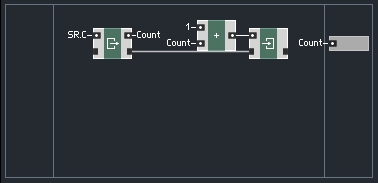
A very common element in Core design is a counter. Counters can easily be modified to create phase accumulators for oscillators, timers for envelopes, index counters for delays, and many other useful DSP elements. I’ll be using both the SR.C and Quick Buses in this example.
Here is the most basic counter available:
This structure simply outputs the number of samples that have occurred since the ensemble was opened. This structure can be modified to reset the count very easily:
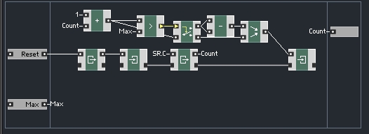
The Reset input triggers a Read module. Since the Read module is not connected via a Latch input to any other module, there is no way to write to that particular value, hence the value get initialized to zero and stays there. The Read module feeds directly into the Write module, which is connected via a Latch to the other modules in the macro, so they all share a value. This achieves the task of resetting the counter to zero.
Note that the Count value is simply sent directly to the output before adding 1 to the value. The reason for this is simple. The reset will most likely occur as an event being sent from Primary. Since events happen in between the ticks of the audio clock, the first output of this counter after a reset will be a zero.
If the trigger to reset happens to be an audio signal, the events happen simultaneously, or in this case, in an order specified by the latch connections. Thus, the value is written to zero, then read and output, then added to 1 and stored for later use. Either way, the first output after a reset is always equal to zero.
This type of counter is similar to what you would use to keep track of time in an envelope structure, for example.
The counter can be further modified to output values only within a certain range, looping through those values instead of increasing permanently. This can be done in any number of ways, according to the user’s needs, but here is a basic example:
The value Max is chosen by the user and represents the maximum value to output. This type of counter can be used for Delay lines, amongst other purposes. The Count+1 value is routed to either subtract itself (IE restarting at zero) or simply be passed directly to the Merge module.
ARRAYS
An Array module is used to store values. They can be used for many of the same purposes as a Primary Event Table or Audio Table. Arrays have an advantage over those modules, however, which is a far more flexible design for writing and reading values.
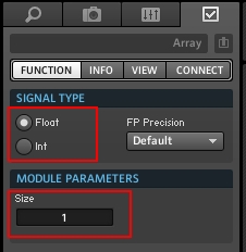
You can set the number of variables an Array can keep track of at once in the properties:
You can also choose whether the Array module will store integers, or floats.
The easiest way to interface with arrays is to use two macros from the Expert Macros -> Memory menu: Read [] and Write []:
These macros work similarly to the Built-In Modules Read and Write that we went over in the previous tutorial. The main difference is that with Arrays you also need to supply an index value to tell Reaktor which variable to read or write.
Like before, the latch inputs and outputs can be used to force an order of operations in structures that may otherwise be vague due to Core’s simultaneous event processing.
That’s all for this week, in the next tutorial, we’ll finally get into building some structures using the concepts we have learned so far.


 YOUTUBE