
Reaktor Tutorials
Wave Digital Filters II - Tube Diode
DEFINING THE SERIAL ADAPTOR
A series adaptor contains two ‘children’, which can be one port elements or even other adaptors. The adaptor receives the ‘wave up’ signal and port resistance values from each child. In addition, they must provide a ‘wave down’ signal to each child macro.
Like the one port elements, adaptors also have their own wave up, wave down, and port resistance values.
Initially, I created a macro that contained all of these elements to use as a series adaptor but the implementation in Reaktor proved to be less than intuitive in my opinion. The reason for this is that each parent is receiving information from and sending information to it’s children, which can create feedback loops for the unwary user.
I wanted to create a framework that could be re-used easily to create a wide variety of WDF structures so I opted to instead create two macros for dealing with the inputs and the feedback loops of an adaptor separately.
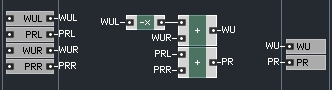
When we do so, the feedforward aspect of the series adaptor becomes remarkably simple – the port resistances from the two children are simply added together and sent to the output as the port resistance for the whole adaptor, meanwhile a simple equation determines the wave up value:
WUp = -WLeftUp+WRightUp
This makes the first half of the series adaptor almost as simple as the one port elements:
In a Reaktor format, all of the wave up signals will of course travel from left to right. WDF structures are built with a tree format, and the ‘root’ of the tree will be the rightmost element. It is at this point (and this point only, to my understanding) that a non-linearity can be added to the structure.
The wave up of the last adaptor module will flow into the non-linearity and the output of the non-linearity then becomes the wave down signal for that adaptor. We can then use the wave down signal of the adaptor to calculate the wave down signal for the two children. So, while the wave up progates from left to right, the wave down value will propagate from right to left.
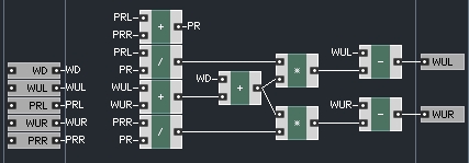
The macro to calculate the wave down signals requires the adaptor wave down,as well as the wave up and port resistance values of the two children.
WDownLeft = WUpLeft – ((WDown+WUpLeft+WUpRight) (PortResLeft/PortRes))
and
WDownRight= WUpRight – ((WDown+WUpLeft+WUpRight) (PortResRight/PortRes))
define the two wave down values. These are called scattering equations.
We wind up, then, with a macro that looks like this:
So this continues the trend of very simple macros, however, connecting them altogether we can achieve some quite complex structures.
TUBE DIODE MODEL
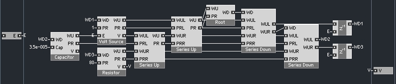
The following tube diode model is described in chapter 12 of DAFX: Digital Audio Effects, edited by Udo Zolzer. The model consists of 1 resistor, 1 capacitor, 1 voltage source (the audio input acts as the E input of this module) 2 series adaptors, and a root non-linearity:
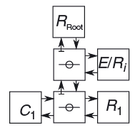
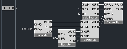
C1 is the capacitor, R1 is the resistor, E/R1 is the voltage source, and the circles with lines thru them represent the series adaptors.
In this diagram, the signals flowing towards the root are the wave up signals, and the signals flowing away from the root are the wave down signals. The first thing we need to do is to connect together our modules such that the wave up values flow towards the root.
The bottom three elements of the diagram look like this in Reaktor:
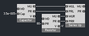
One series adaptor and it’s two children. The resistance and capacitance values are given in the text of Zolzer’s book.
This series adaptor can now be used as a child for the second adaptor:
Next, the root non-linearity mush be calculated, after which we can begin calculating the wave down values:
Here is where splitting the series adaptor into two macros comes in handy, otherwise we would now be getting feedback loops in-between the two series adaptors (and possibly elsewhere as well).
So in the above structure, the wave down signals are calculated for the element closest to the root first, and then are fed backwards into their children. The top series adaptor feeds wave down signals to the voltage source and the bottom adaptor. The bottom adaptor must then calculate the wave down signals for the capacitor and the resistor. Splitting the series adaptor in two lets us keep a somewhat sensible left-to-right structure view, even though at the end, all of the WD1, WD2, and WD3 waves are feeding back into the inputs.
Once the wave down values are calculated, feeding them back into the one port elements can be a confusing task. The resistor and voltage source macros, for instance, need a z^-1 macro in the feedback loop. However, the capacitor and inductor macros will delay the wave down by a sample on their own.
So, in the above structure , the ‘Solid’ parameter of the capacitor macro has been turned off, which signifies that the macro will resolve the feedback loop on it’s own. The same has been done for the inductor model included in the download. For more on the Solid parameter, check out page 113 in the Core manual, specifically section 5.4, Feedback Around Macros.
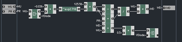
Okay, all that remains is now is to calculate the root linearity itself. This is by far the most interesting aspect of a WDF. Using the code from Zolzer’s book, we arrive at a root macro that looks like so:
Finally, we simply read the ‘V’ output of the resistor to get our output, as shown two pictures up.
CONCLUSION
There are quite a few documented WDF structures available in DSP literature. One of the aspects that really appeals to me is that WDFs are completely modular and so has a lot of flexibility in the design.
To that end, I’ve included a download that includes all of the macros from the last two tutorials, as well as the tube diode for good measure.
Please let me know if you find any errors – the code I am basing this work on was written in Matlab, which I am unfamiliar with so it is possible there are mistakes.
If there is demand for it, this series can continue with parallel adaptors and more complex structures, let me know if you are interested!
