
Reaktor Tutorials
Creating Custom Oscillators in Reaktor Core
This tutorial introduces a generic oscillator design in Reaktor Core than can be used to create a wide variety of oscillator types. Designing in Core is a complicated subject, but I will attempt to explain everything in full detail. Please don’t hesitate to ask for more information on a given subject.
This tutorial also serves as a introductory step towards more advanced oscillator types, including bandlimited oscillator types, phase modulation, frequency modulation, and more.
OSCILLATOR ARCHITECTURE
Most oscillators contain two common elements: a phase accumulator that ramps between -N and N (how fast is determined by MIDI note values), and a function that accepts values between -N and N.
For example, a sine oscillator has a phase accumulator ranging from -π and π, and the value held in the phase accumulator is sent to a sine function. The result is a sine wave.
All work in today’s tutorial will be done in an Audio Core Cell.
PHASE ACCUMULATOR
The phase accumulator is pretty easy to make in Core. We have a few variables that determine the frequency of the accumulator and the range to ramp between. A basic macro implementation would look something like this:
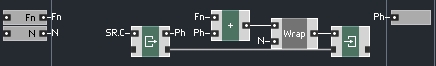
If you are unfamiliar with Core, the text may be confusing (Fn, Ph, SR.C and N). The name for these is ‘Quick Bus’ and they are simply replacements for wires, usually used to make code more clear. Anywhere there is an output labelled with the same text as an input, that input/output pair are connected.
You can create a Quick bus or connect to an existing one by right-clicking on any input or output and selecting the appropriate command.
So, what do these Quick Busses stand for? N and Fn are variables that control the range and speed of the phase accumulator, respectively. Ph is a value that stores the current phase of the phase accumulator. SR.C is a special case, it stands for Sample Rate Clock, and it triggers at the sampling rate, as the name implies!
As with a Quick Bus, you can connect to the SR.C by right-clicking on an input.
To understand the use of the SR.C, I want to focus on these two modules:

On the left is a Read module, on the right, a Write module. These modules are an important part of how Core works. Notice the bottom inputs and outputs that are square (as opposed to circles). These ins and outs are used to associate read/write modules to each other, and to specify in which order the modules trigger. All Read and Write modules connected by their bottom ports (called latches) contain the same value.
For example, in the first picture, the Read module is triggered at every sample tick by the SR.C. It outputs the Ph Quick Bus, which is immediately read as the current phase of the accumulator and sent to the output. The Ph bus also calculates the next value of the accumulator by adding Fn to the phase, and then wrapping the final using the Wrap macro. This wrapped value will be triggered by the next SR.C, and the whole process repeats ad infinitum.
Now let’s briefly cover the Wrap macro:
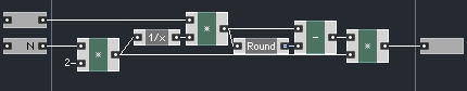
The ‘Wrap’ macro takes any value and wraps it between a range of -N and N (for example, if N = 1 and the input is 1.05, the output will be -0.95). It is a slightly modified version of a factory macro, which had the exact same function, except in my version N is variable and can be defined by the user. In the factory version, it always wrapped between -π and π and was named 2pi wrap. The original can be found, amongst other places, inside the factory Sin macro.
The last thing to cover is to set the Fn and N values properly. The N value is actually determined by the type of oscillator, usually it is equal to either 1 or π. The N value is necessary to properly determine the value of Fn, however. Here’s a macro I wrote, Calc, that accepts a Pitch and an N value, and outputs Fn and N:
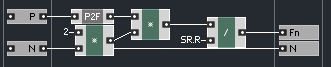
The SR.R is another special bus that outputs the sampling rate (the frequency of the SR.C). You can connect to it by right-clicking on an input.
Here, we are merely calculating the distance the oscillator must travel in one second, and dividing by the number of samples in a second to discover how far the Ph accumulator should travel per sample, Fn.
OSCILLATOR FUNCTIONS
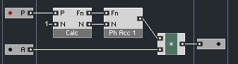
Using the macros introduced in the previous section, it is easy to create oscillators. We simply take the output of the phase accumulator and shape it into whatever oscillator type we like. Here is an implementation that will function like a Primary Sine Oscillator:
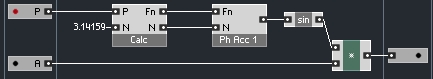
The user simply supplies the Pitch and Amplitude of the oscillator.
In fact, you can even use the phase accumulator as an output. The result is what is referred to as a ‘naive ramp’:
On a scope, it looks like an inverted sawtooth, and it sounds like one too. Unfortunately, this implementation of a ramp/saw wave has some unpleasant characteristics, namely, it suffers from a large amount of aliasing. Check the tutorial on aliasing here.
Similarly, a ‘naive pulse’ oscillator is quite easy to build:
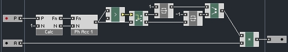
This one is a simple squarewave – it is equal to -1 if the phase accumulator is less than 0, and equal to 1 otherwise. This oscillator will also suffer from aliasing – many oscillators will if you do not take care. In future tutorials, I will show how to extend today’s work to create bandwidth limited oscillators that do not have this problem.
CONCLUSION
Core is a difficult subject. If there are any questions on implementations, what certain modules do, or where to find them, please let me know in the comments.
There are many places we can go from here. The phase accumulator structure we designed today can be easily extended to include controls like phase or frequency modulation. In addition, there is the subject of bandwidth limiting and more to cover as well. In future installments, we will cover all of these and more!
